


|
|
||
|
You might find it surprising that the "Hello World!" chapter comes at the end of any tutorial, but this is related to the realities of embedded systems, where human interactions require the highest sophistication of involved components, which might be not just more complex, but also more expensive than the embedded computer itself. Still, displaying a message to the user is something that can be implemented from scratch and we will explore how this can be done - we will leave things like playing encoded video aside...
In order to display anything we need an external display that will be connected to the board. There are many alphanumeric and graphical displays available on the market and among the standard (and relatively inexpensive) solutions are LCD displays based on the Hitachi HD44780 controller. One of the most popular variants allows to display 2 lines of text with 16 characters in each line and this is what we will target here - but before we will delve into this we will need to see how Ada handles strings.
Ada supports the String data type as one of its standard types, so it is possible to intuitively use constructs like this:
Message : String := "Hello";
The above looks straightforward, but works a bit differently than in other high-level programming languages. In Ada String is an array type defined like this:
type String is array (Positive range <>) of Character;
In other words, strings are regular arrays of characters. This means that, unlike in Java, strings in Ada do not automatically involve the use of dynamic memory (of course, with full language run-time it is still possible to allocate such arrays dynamically) and, unlike in C, they do not force the programmer to deal with pointers. These features make strings very convenient to use also in a constrained embedded environment. On the other hand, the array nature of strings has an impact on how strings can be handled - in particular, such strings cannot be easily resized and this is why full Ada offers additional types that make such tasks easier.
In any case, the example above defines the variable Message that is an array of Characters, created and immediately initialized with size 5, where the first character with index 1 is 'H'. Note that, unlike in C, strings do not have any terminating character appended to them, this array really has length 5.
You can access individual characters of a string (for both reading and writing, if necessary) by just indexing the array:
C : Character := Message (1);
This creates a variable that will contain a copy of the first character in the string, which is character 'H'. Characters in Ada are not numbers - they are enumerations, but have standardized positions and correspond to the Unicode character set. The value of each character (or any other enumeration) can be extracted with the attribute 'Val of type Character, like here:
Character'Val (C)
The reverse operation exists as the attribute Character'Pos.
In other words, this simple loop (with Code being some integer variable):
   for I in Message'Range loop
      C := Message (I);
      Code := Character'Val (C);

      -- ...

   end loop;
allows to iterate over the string content and extract the code of each character - in our case the codes will be 72, 101, 108, 108 and 111, because these are the Unicode and ASCII codes for letters in "Hello" - again, note that there is no artificial terminating character and the string "Hello" has length 5. We will need similar constructs for managing the LCD display.
Just to complete this "string theory" - strings (just like other arrays) can be concatenated and sliced, so:
   Bigger_Message : String := Message & " World" & '!';
   Middle_Part : String := Bigger_Message (8 .. 9);
Bigger_Message will contain the string "Hello World!" and Middle_Part will be a short "or". Note that even though arrays cannot be resized, they can be initialized by values which lengths are not necessarily static. Such operations might be necessary for composing and formatting messages at run time.
The displays compatible with the HD44780 controller should operate with a wide range of voltages and can be safely used with both 5V and 3.3V devices (the Arduino Due operates with 3.3V). It is not clear if this is true for all such displays, as many of them have descriptions that assume 5V powering. Note that there are special level shifters that can help connecting devices from different voltage domains, but ironically such level shifters can be more expensive than the whole display, so it is better to shop carefully and aim for the display that can be really connected directly in the 3.3V domain, although it might be more difficult to get proper contrast with the lower voltage range. Do not hesitate to experiment or ask your local electronics guru for advice.
Apart from powering and contrast adjustment, the display has the following control and data connectors:
It might appear that 11 lines is a lot (in fact, this will almost exhaust the set of pins that we have defined in previous chapters), but this is a matter of perspective - the ARM microcontrollers like the one in Arduino Due or Nucleo-144 have very large numbers of I/O pins and allocating 11 of them for display control is not a problem; on the other hand, this can be wasteful in terms of physical connections or cabling that have to be prepared and for this reason the display can be also operated in 4-bit mode, where only half of the data lines need to be used, at the price of slightly more complex communication patterns. We will explore the 8-bit operation as it is simpler at the programming level, the 4-bit version is "left as an exercise to the reader" and surely a complete documentation (a datasheet) for the display controller will be needed for this.
We will start by allocating board resources (pins) to control the display and the following associations are convenient when connecting the display side-by-side with the board:
We can express this allocation with the following definitions in the newly created LCD package (in the body):
   Line_RS : constant Pins.Pin_ID := Pins.Pin_2;
   Line_RW : constant Pins.Pin_ID := Pins.Pin_3;
   Line_E  : constant Pins.Pin_ID := Pins.Pin_4;
   Line_D0 : constant Pins.Pin_ID := Pins.Pin_5;
   Line_D1 : constant Pins.Pin_ID := Pins.Pin_6;
   Line_D2 : constant Pins.Pin_ID := Pins.Pin_7;
   Line_D3 : constant Pins.Pin_ID := Pins.Pin_8;
   Line_D4 : constant Pins.Pin_ID := Pins.Pin_9;
   Line_D5 : constant Pins.Pin_ID := Pins.Pin_10;
   Line_D6 : constant Pins.Pin_ID := Pins.Pin_11;
   Line_D7 : constant Pins.Pin_ID := Pins.Pin_12;
The above definitions are very important in that they decouple the meaning of each line from its physical allocation - thanks to this, if you decide to reconnect the display to some other pins or in other order, this will be the only place that will have to be changed to reflect it. All other parts of the code will refer to the logical names like Line_RS instead of Pins.Pin_2, and so on. Such associations can be also parameterized and performed at the initialization phase, but we will not need this flexibility, the static definitions above will be sufficient.
Before we will start communicating with the display, it will be helpful to have this definition:
type Byte is mod 2**8;
This is similar to the Word type from the Registers package, but is intended to handle 8-bit data chunks (bytes). Note that it is a numeric type that in addition to normal arithmetic (modulo 256, of course) supports also logical operations at the bit level. With this definition we can write the following helper procedure:
   procedure Write (RS : in Boolean; Data : in Byte) is
   begin
      Pins.Write (Line_E, True); -- E high

      Pins.Write (Line_RS, RS);
      Pins.Write (Line_RW, False); -- RW low (write mode)

      Pins.Write (Line_D0, (Data and Registers.Bit_0) /= 0);
      Pins.Write (Line_D1, (Data and Registers.Bit_1) /= 0);
      Pins.Write (Line_D2, (Data and Registers.Bit_2) /= 0);
      Pins.Write (Line_D3, (Data and Registers.Bit_3) /= 0);
      Pins.Write (Line_D4, (Data and Registers.Bit_4) /= 0);
      Pins.Write (Line_D5, (Data and Registers.Bit_5) /= 0);
      Pins.Write (Line_D6, (Data and Registers.Bit_6) /= 0);
      Pins.Write (Line_D7, (Data and Registers.Bit_7) /= 0);

      Pins.Write (Line_E, False); -- E low to trigger data transfer
   end Write;
The Write procedure above performs the write operation with the given byte of data and allows selecting the RS line level, so that it can be used for both control instructions and data transfers. Note that the given byte Data is decomposed into individual bits by means of logical and operator and each bit is set separately on its corresponding output pin. It is possible to allocate pins so that the whole group of 8 pins will be handled by a single I/O port and it is even possible to do this so that the order of bits will be the same and as a result the whole output operation could be performed in a single line of code (perhaps with some shifting), but even though it can look attractive from the coding perspective, do not fall into this trap - there is certainly no performance benefit from this (especially in the context of artificial delays that you will see in a moment) and the price to be paid for the reduction of several lines of code is very high: it will not be possible to easily reconnect the display to other pins or in a different order and every such redesign at the physical level will involve corrections in the code that deals with data transfer. Such designs are very fragile and can be justified only when a truly atomic modifications of a set of pins are needed. This is not the case with this display, as the actual data transfer is triggered by the falling edge on line E - note that this is done at the end of Write, when all data lines are already set.
The Write procedure above can be a basis for all operations supported by the display - for example, the Function Set instruction that allows to set the data length and the number of display lines needs to have bits 5, 4 and 3 set for 8-bit operation and 2-line display (check this in the display datasheet) can be implemented like this:
   procedure Function_Set is
      D : constant Byte :=
         Registers.Bit_5 or
         Registers.Bit_4 or -- 8-bit interface
         Registers.Bit_3;   -- 2 lines display
   begin
      Write (RS => False, Data => D);
   end Function_Set;
Note how the data byte was constructed from individual bits - we have reused constant definitions that were already created in the package Registers. The Write procedure is called with named parameter associations for higher readability - the RS line is set low during this operation because Function Set is a control instruction.
You should check with the datasheet of the display controller what are the expected bit patterns for the other instructions: Entry Mode Set, Clear Display and Display On.
One of the inconveniences of the HD44780 display is that it enforces some delays for each instruction and it is not possible to send another instruction before the previous one finishes execution. The execution times are documented, so the easiest programming approach is to insert artificial delays in the program so that the display has enough time to process each instruction before the next one is sent. It is also possible to query the display for its busy flag, but since the read operation also involves some artificial delay, it is not a satisfactory solution and the most popular way to control this display is with program delays. We will use the following helper procedure to create generous 20ms delays (this value is conveniently aligned with the 10ms of our system timer resolution - you can change both values if required):
   procedure Pause is
      Now : constant Utils.Time := Utils.Clock;
      Wait_Time_Millis : constant := 20;

      use type Utils.Time;
   begin
      Utils.Delay_Until (Now + Wait_Time_Millis);
   end Pause;
With this helper and the proper implementation of all display instructions, we can write the complete initialization procedure, with the order of invocations as required by the display datasheet:
   procedure Initialize is
   begin
      Pause;

      Pins.Enable_Output (Line_RS);
      Pins.Enable_Output (Line_RW);
      Pins.Enable_Output (Line_E);
      Pins.Enable_Output (Line_D0);
      Pins.Enable_Output (Line_D1);
      Pins.Enable_Output (Line_D2);
      Pins.Enable_Output (Line_D3);
      Pins.Enable_Output (Line_D4);
      Pins.Enable_Output (Line_D5);
      Pins.Enable_Output (Line_D6);
      Pins.Enable_Output (Line_D7);

      -- initial sequence
      Function_Set;
      Pause;
      Function_Set;
      Pause;
      Function_Set;
      Pause;

      -- functional initialization
      Function_Set;
      Pause;
      Display_On;
      Pause;
      Clear_Display;
      Pause;
      Entry_Mode_Set;
      Pause;
   end Initialize;
Note that there is a pause after each control instruction.
With all these control bits and pieces already in place, we can attempt to implement the actual display (printing) commands. The display has 2 lines with 16 characters in each line, so the following types will be used to express screen coordinates:
   type Line_Number is range 1 .. 2;
   type Column_Number is range 1 .. 16;
The characters are displayed with two-phase operation: first, the "address" of the character needs to be established with the control instruction and then the character code can be transmitted to the display - it will appear at the right place, depending on the address. The logical address of the first character in first line is 0x0 and the second line occupies addresses starting from 0x40. These facts lead us to the following definition for the single-character Print procedure:
   procedure Print (Line : in Line_Number; Column : in Column_Number;
     C : in Character) is
      Address : Byte;
   begin
      if Line = 1 then
         Address := Byte (16#00# + Column - 1);
      else
         Address := Byte (16#40# + Column - 1);
      end if;

      -- set DDRAM address
      Write (RS => False, Data => Registers.Bit_7 or Address);
      Pause;

      -- write data
      Write (RS => True, Data => Byte (Character'Pos (C)));
      Pause;
   end Print;
Note that the display expects character codes that correspond to the ASCII codes for the lower half of the page and this, by coincidence, corresponds to the values of character enumerations in Ada.
The version of the Print procedure for strings is similar and relies on the fact that the cursor, maintained internally, automatically moves to the right after each written character. We only need to include some protection against lengthy strings that might fall out of the display range:
   procedure Print (Line : in Line_Number; Column : in Column_Number;
     Msg : in String) is
      Address : Byte;
      Current_Column : Column_Number := Column;
   begin
      if Line = 1 then
         Address := Byte (16#00# + Column - 1);
      else
         Address := Byte (16#40# + Column - 1);
      end if;

      -- set starting DDRAM address
      Write (RS => False, Data => Registers.Bit_7 or Address);
      Pause;

      -- write data
      for I in Msg'Range loop
         Write (RS => True, Data => Byte (Character'Pos (Msg (I))));
         Pause;

         exit when Current_Column = Column_Number'Last;
         Current_Column := Current_Column + 1;
      end loop;
   end Print;
That's it!
It is easy to use the LCD package and the only additional requirement that might not be immediately obvious is that the system timer has to be operational as well, as it is used for artificial communication delays. A basic program that displays the greetings can be written like this:
with LCD;
with Utils;
package body Program is
procedure Run is
begin
Utils.Enable_Interrupts;
Utils.Enable_System_Time;
LCD.Initialize;
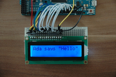
LCD.Print (1, 1, "Ada says ""Hello""");
-- ...
The double quotes is a way to inject a quote in the string, so the actual string that is displayed is:
Ada says "Hello"
This string has 16 characters and will fill the whole line of the display.
We might finish this chapter with the single static message above, but the LCD package, even with its very basic interface, allows implementing simple animations as well (and we still have a second display line to use!). The following loop will make the arrow character '>' appear to move from left to right by displaying it in one place only for the time Wait_Time_Millis and by clearing it with a space character after that:
      Next_Time := Utils.Clock;

      -- arrow moving from left to right
      for I in LCD.Column_Number'Range loop
         LCD.Print (2, I, '>');

         Next_Time := Next_Time + Wait_Time_Millis;
         Utils.Delay_Until (Next_Time);

         LCD.Print (2, I, ' ');
      end loop;
Note that the Delay_Until pattern is very robust and will operate properly independently on the delay that is artificially inserted in the implementation of procedure Print, even if the length of that hidden delay is changed.
Previous: System Timer, next: Mixing Ada With C and C++.
See also Table of Contents.