


|
|
||
|
In the previous chapters we have managed to design the most basic utility functions for controlling digital pins, for both output and input. These basic utilities are useful enough to tackle some real control system that interacts with its environment.
As a simple, but complete example, we will investigate the fan control system. Assume that the fan has the capability to operate in three different modes:
Imagine also that the fan has two buttons - "up" and "down" - that are used to control its operation. The intuitive rules are that:
Note that the above rules are exhaustive in the sense that there is no other possibility that would have to be considered. All these rules can be described in the following diagram:
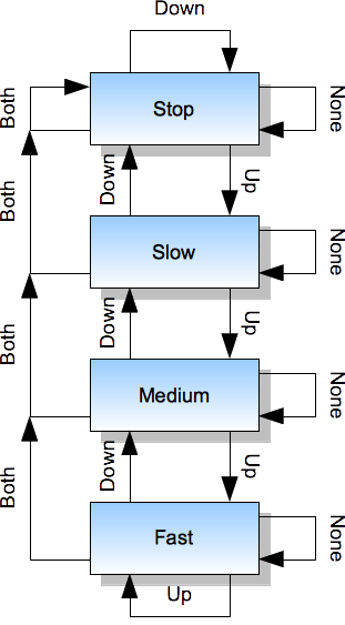
The system described above is a finite state machine, which is a name for a broad family of systems that have a well understood theory behind them. Many different systems can be described and implemented following the rules that are common across this family.
The implementation of this system with any of our boards is very simple. We can use digital inputs to handle buttons. The pull-up mode is very useful for this, as it minimizes the number of necessary connections - the disconnected pin (reading "high" due to pull-up) will be interpreted as button not being pressed, whereas the pressed button will short the pin to the ground (reading "low", be careful that here the "low" state means that the button was activated, this is also known as the active low configuration). We can also use digital outputs to handle different motor speeds and for the simplicity we will assume that there are three distinct control lines that can switch the motor appropriately. The following allocation of pins will be appropriate for this system:
There are several possible strategies for implementing such a system in Ada and in this chapter we will explore only one of them.
We should note that the system needs to be aware of its current mode of operation, known as "state", because it is the state, together with the inputs, that influence the decision on what should be done next. We have identified four states and they can be described in Ada with this enumeration type:
type Fan_State is (Stop, Slow, Medium, Fast);
We have also exhaustively described rules for handling buttons - their possible current states (yes, states) can be also described with the enumeration type, similarly to how they are described in the diagram above:
type Buttons_State is (None, Up, Down, Both);
The similarity of these two definitions is not intentional and we will not delve into philosophical discussions on whether they should be kept separate at all. We will stay with intuitive notion that Fan_State represents the current activity of the system and is the internal property of the system, whereas the Buttons_State describes control commands that come from external sensors. In any case, the above definitions can be accompanied with these helper procedures:
   procedure Control_Motor (S : in Fan_State) is
   begin
      case S is
         when Stop =>
            -- stop the motor
            Pins.Write (Pins.Pin_4, False);
            Pins.Write (Pins.Pin_5, False);
            Pins.Write (Pins.Pin_6, False);

         when Slow =>
            -- first circuit on
            Pins.Write (Pins.Pin_4, True);
            Pins.Write (Pins.Pin_5, False);
            Pins.Write (Pins.Pin_6, False);

         when Medium =>
            -- second circuit on
            Pins.Write (Pins.Pin_4, False);
            Pins.Write (Pins.Pin_5, True);
            Pins.Write (Pins.Pin_6, False);

         when Fast =>
            -- third circuit on
            Pins.Write (Pins.Pin_4, False);
            Pins.Write (Pins.Pin_5, False);
            Pins.Write (Pins.Pin_6, True);
      end case;
   end Control_Motor;

   procedure Read_Buttons (B : out Buttons_State) is
      B_Down : Boolean;
      B_Up : Boolean;
   begin
      Pins.Read (Pins.Pin_2, B_Down);
      Pins.Read (Pins.Pin_3, B_Up);

      if not B_Down and not B_Up then
         B := Both;
      elsif not B_Down and B_Up then
         B := Down;
      elsif B_Down and not B_Up then
         B := Up;
      else
         B := None;
      end if;
  end Read_Buttons;
Note that the Read_Buttons procedure uses reversed logic for interpreting buttons - for example the not B_Down expression checks if the state read on pin 2 was False, which means that the button was pressed. This is the active low strategy that is a result of pulled-up configuration of the input. It might not be intuitive at the beginning.
Note also that these two procedures use different kinds of conditional statements - the actual choice is frequently a matter of engineering judgement, but the case statement is a very readable choice for handling enumeration values.
With this scaffolding in place, the main program is still a bit lengthy, but has a structure that clearly corresponds to the diagram above:
   procedure Run is
      Current_State : Fan_State;
      Buttons : Buttons_State;
   begin

      -- initialize the device
      Pins.Enable_Input (Pins.Pin_2, Pins.Pulled_Up);
      Pins.Enable_Input (Pins.Pin_3, Pins.Pulled_Up);
      Pins.Enable_Output (Pins.Pin_4);
      Pins.Enable_Output (Pins.Pin_5);
      Pins.Enable_Output (Pins.Pin_6);
      Current_State := Stop;
      Control_Motor (Current_State);

      -- repeat the control loop
      loop
         Read_Buttons (Buttons);

         case Current_State is
            when Stop =>
               case Buttons is
                  when None | Down | Both =>
                     -- nothing to do
                     Null;
                  when Up =>
                     Current_State := Slow;
               end case;

            when Slow =>
               case Buttons is
                  when None =>
                     -- nothing to do
                     Null;
                  when Down | Both =>
                     Current_State := Stop;
                  when Up =>
                     Current_State := Medium;
               end case;

            when Medium =>
               case Buttons is
                  when None =>
                     -- nothing to do
                     Null;
                  when Down =>
                     Current_State := Slow;
                  when Up =>
                     Current_State := Fast;
                  when Both =>
                     Current_State := Stop;
               end case;

            when Fast =>
               case Buttons is
                  when None | Up =>
                     -- nothing to do
                     Null;
                  when Down =>
                     Current_State := Medium;
                  when Both =>
                     Current_State := Stop;
               end case;
         end case;

         Control_Motor (Current_State);

         Utils.Waste_Some_Time;
      end loop;
   end Run;
Note that the when alternative of the case statement has the ability to group several values in a single branch.
You might also note that the Control_Motor procedure is written in a way that can cause potential switching problems. For example, in a transition from Fast (when pin 5 is "high") to Medium (when pin 4 is "high"), pin 4 is set before pin 5 is cleared and as a result there can be a spike caused by two pins being at a "high" state at the same time, which is contrary to our original assumption. In real control systems there might be a requirement for some specified dead time during the transition, when neither line is active, to avoid the conflict. Can you fix it in this simple program?
The above strategy of implementing finite state machines relies on the source code structure to reflect the design and rules of all state transitions. This approach has the advantage that the logic of the program is encoded in its statements and this makes it easier to understand when following its line-by-line execution in the debugger. On the other hand, the state transitions are entangled with the code and are more difficult to replace with other transition patterns by means of a simple re-configuration. In later chapters we will explore an alternative strategy that has this trade-off the other way round.
In any case, the above code does not contain any elements that would be hardware-dependent within the set of our boards. The necessary, even though very simple, Hardware Abstraction Layer (HAL) is already provided by the Pins package, with support from Registers and the linker script that were extended for the whole set of pins in the previous chapter.
Previous: Digital Input, next: Constant Values.
See also Table of Contents.